Reimaged XF551 Circuitry in a SF314 Disk Drive Case
Description
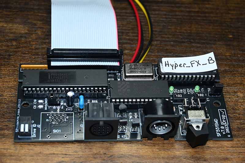
Some years ago I was given a challenge to somehow shove all the XF551 main circuitry into XE130(Atari ST520) themed Atari SF314 disk drive case. I thought the individual was crazy, no way it would fit. But he wanted a 3.5" drive in a appropriately themed Atari XE case without the heft of the Atari XF551 5.25" drive. So I took a second look at the possiblity. And lost a few hairs off my head in the next few months as I painstakingly recreated the XF551 circuit onto a pcb less than half the size of the original. Using the SF314 case he sent me I was finally able to everything to fit. Along the way I had to substitute for some parts that were no longer available for the SF314 to keep it as original as possible. Some parts still had to be salvaged from an XF551 and now the SF314. But I did it. I understand the drive conversion I did is still going strong. I felt pretty proud of myself all in all. Until nearly a year later when I learned that there were at least 3 different versions of the Atari SF314. Some had longer disk drives/shorter pcbs, some had dual power and later ones had only +5V and used a different power jack etc. I invented new cuss words to use towards Atari. I struggled over the last three years or so with making a pcb that would handle all the differences or at least make them mute. COVID, a family death and will probate, family dynamics, cancer and to put the icing on the cake a natural gas royalty payment dispute that dragged on for nearly a year all took it's toll on my health, time and to some degree my sanity. But finally I think I have reached a point that I might have that magical pcb ready for release.
This is not an easy build and is not inexpensive to do. Some newer parts are even now becoming hard to source
Tips
Some things to understand about this build:
This is a fairly complicated build requiring a solid level of SMD soldering and cable building. I've tried to keep it as simple as possible but if you don't have the soldering/cable building skills, have someone who does do it. Pay them well, because if they do a good job they will have earned it and more.
Hard to find/salvage parts list:
- XF551 Items: Intel 8040/8050, WD1772PH, 27C64 Eprom, 8.333MHz OSC, Power Switch, Drive ID Piano Dip Switch
- SF314 Items: SF314 Case,drive and dual +5V/+12V power supply with Power Jack Male 5pin DIN or 800XL/130XE Power Jack if SF314 is +5V only and Atari 800XL/130XE power supply
- CUI SDF-130J Female DIN 13pin pcb mount Jack x2(This has recently been discontinued by manufacturer)
- SIO Cable 1FT and 13pin DIN Midi 4.9FT Cable for Fender Stratocaster Roland GC-1
BOM will have links for possible sources.
Files
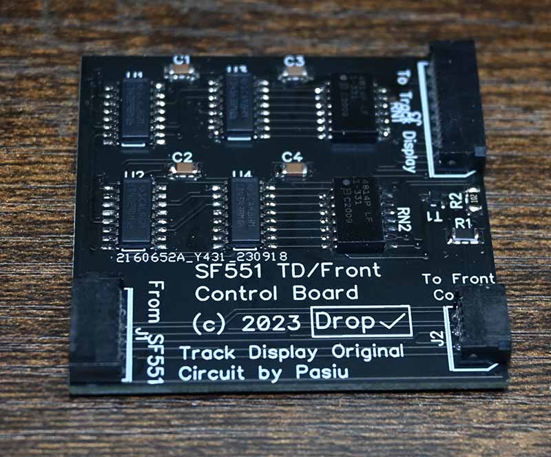
SF551 Control Board Accessory PCB
Description
This control board takes in signals from the SF551 Drive pcb and develops signals for a dual 7-segment track display, reset switch, drive id switch and bios switch. It is mostly SMD parts so skill in SMD soldering is needed, but should not be very hard. You will need to also provide the track display board and control panel from the XF551 board. It is compatible here too.
Skill is needed to install these two boards into an SF314 case
Tips
You will need the two XF551 Accessory boards. They are compatible with the SF551 Control Board Accessory PCB.
Files